TECHNICAL DRAWING
As one of the most useful tools in conveying information to manufacturers, technical drawings are an essential part of both the design and manufacture process in modern day engineering. Drawings can be produced bespoke to your needs and tailored to suit whether the information is to be used for manufacturing, as a verification of the design or to check existing components dimensionally.
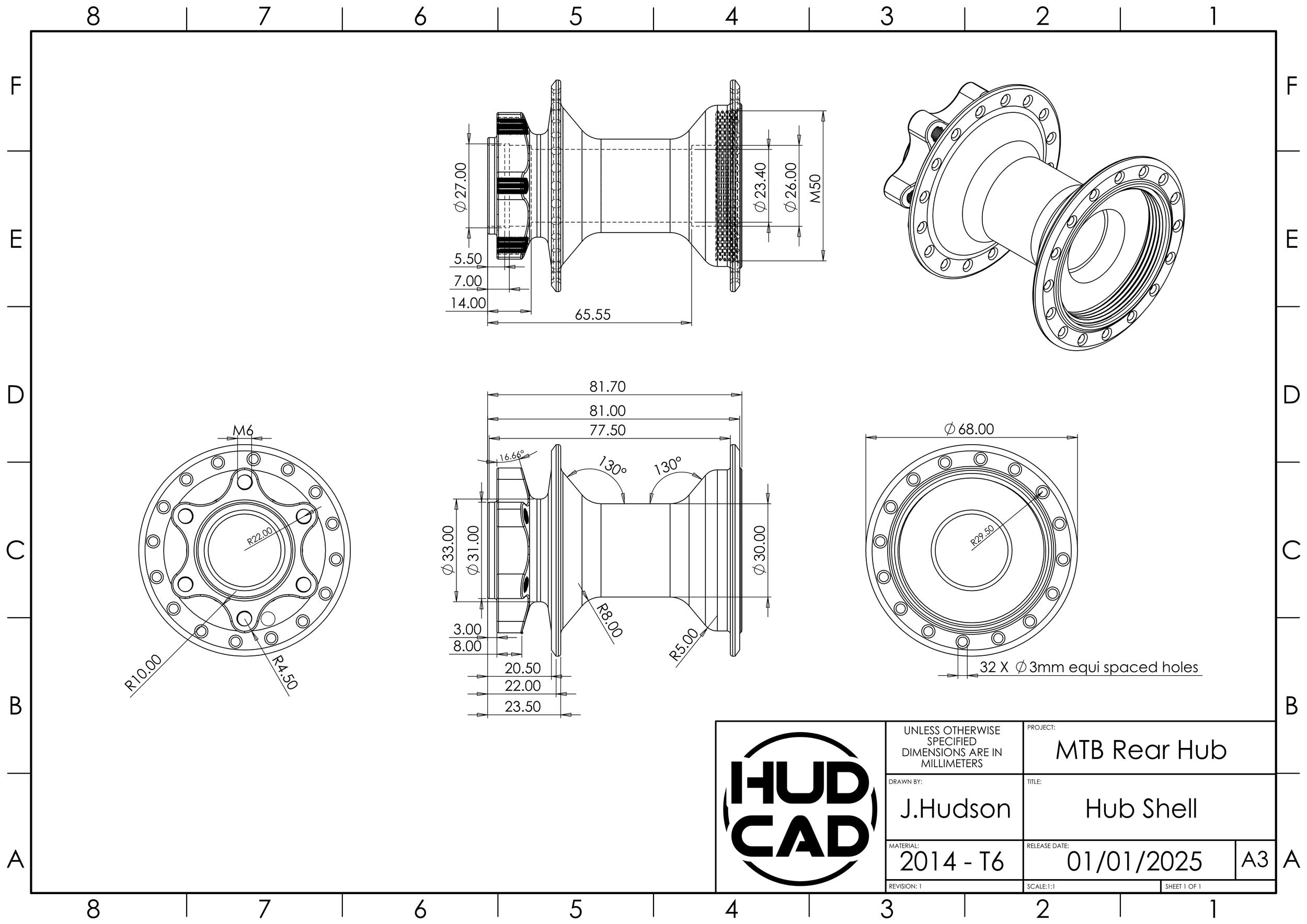
DIMENSIONED DRAWINGS
A fully dimensioned drawing is a type of technical or engineering drawing used to describe the shape, size, location and any other geometric characteristics of a component. This type of drawing is commonly used as a crucial form of communication to verify the design or for production to manufacture a part as it was intended to be by the designer.
Assembly DRAWINGS
This type of drawing is a technical illustration used to demonstrate how multiple components fit together to form a final product. These drawings will aid in the assembly and manufacturing process, acting as a clear guide for everyone involved, as well as playing a crucial role in project management to prevent error and reduce cost.

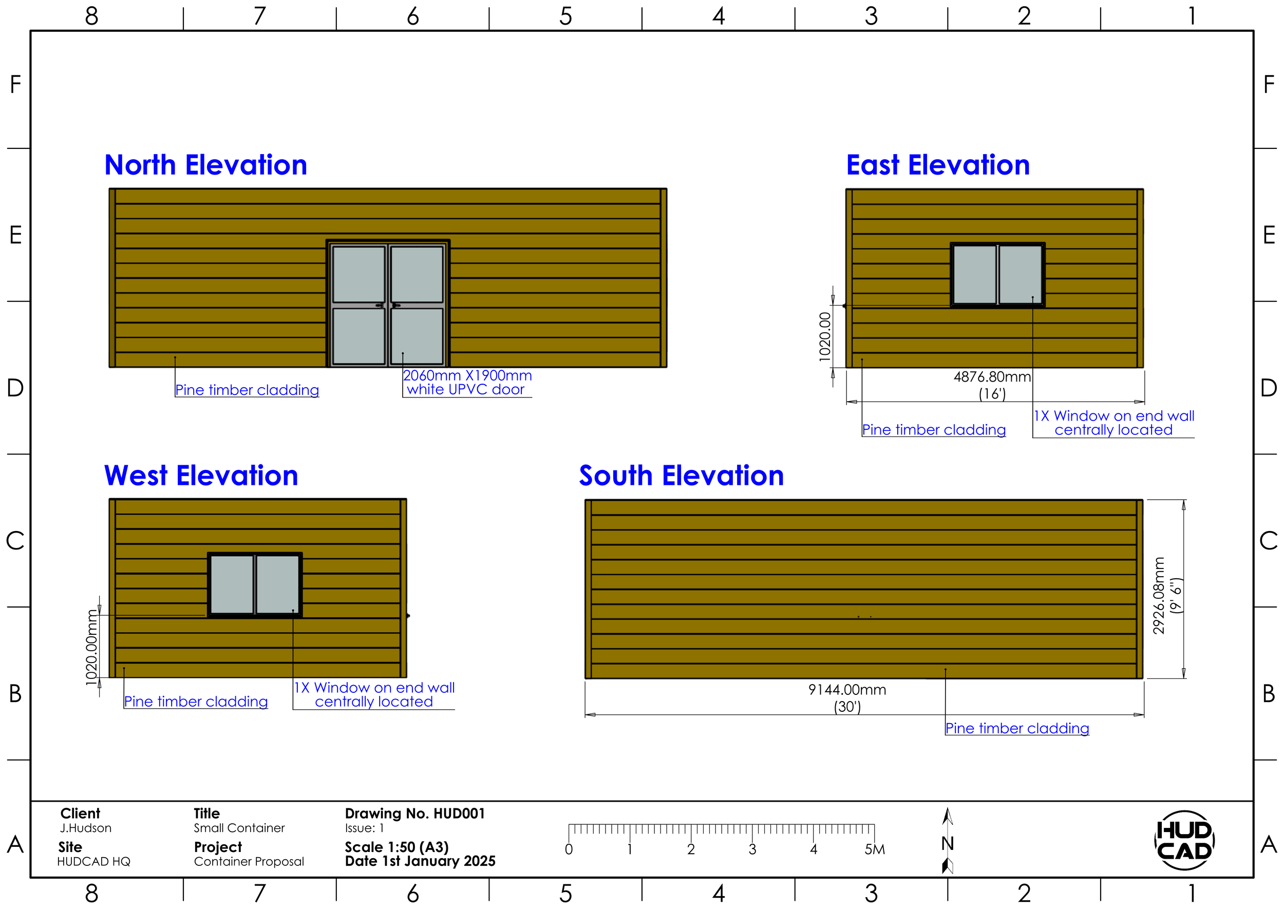
Elevation DRAWINGS
An elevation drawing is a two dimensional, straight on view of a buildings exterior side, highlighting key features such as windows, doors and the materials used in its manufacture. These drawings provide a flat, realistic, representation of one face of the structure that can be used to help architects, builders or clients better visualise the design from a specific direction.
They are commonly used in the proposal of planning permission to show how a new building will fit into its surroundings. Information displayed on drawings can be tailored to a client or projects exact needs and portray specific dimensions, building features and material grades.